Bonus: The Saga of the Silty Soakaway: Vol. 2
I feel like maybe we just haven’t talked enough about floors. We love floors, always have always will. We also love drainage. Combine the two and whoopee, we’ve got a party.

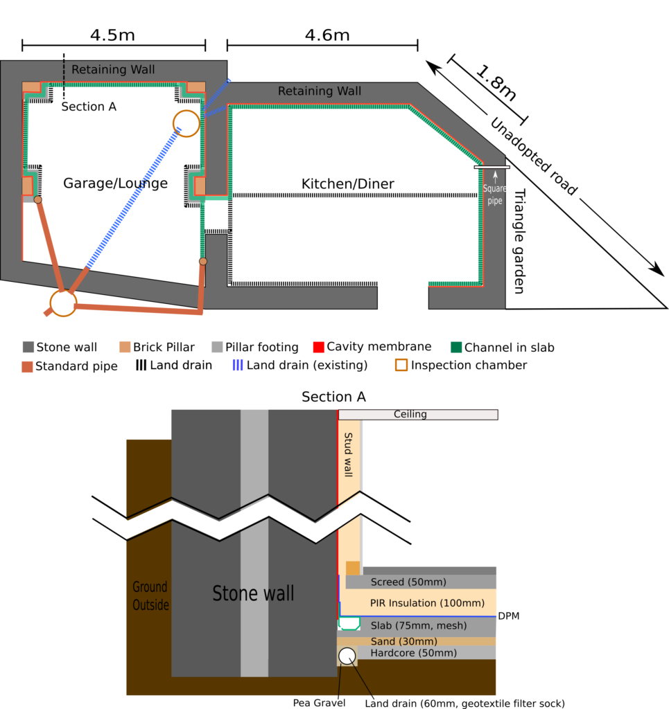
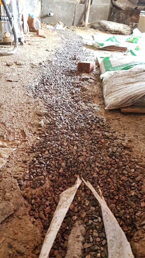
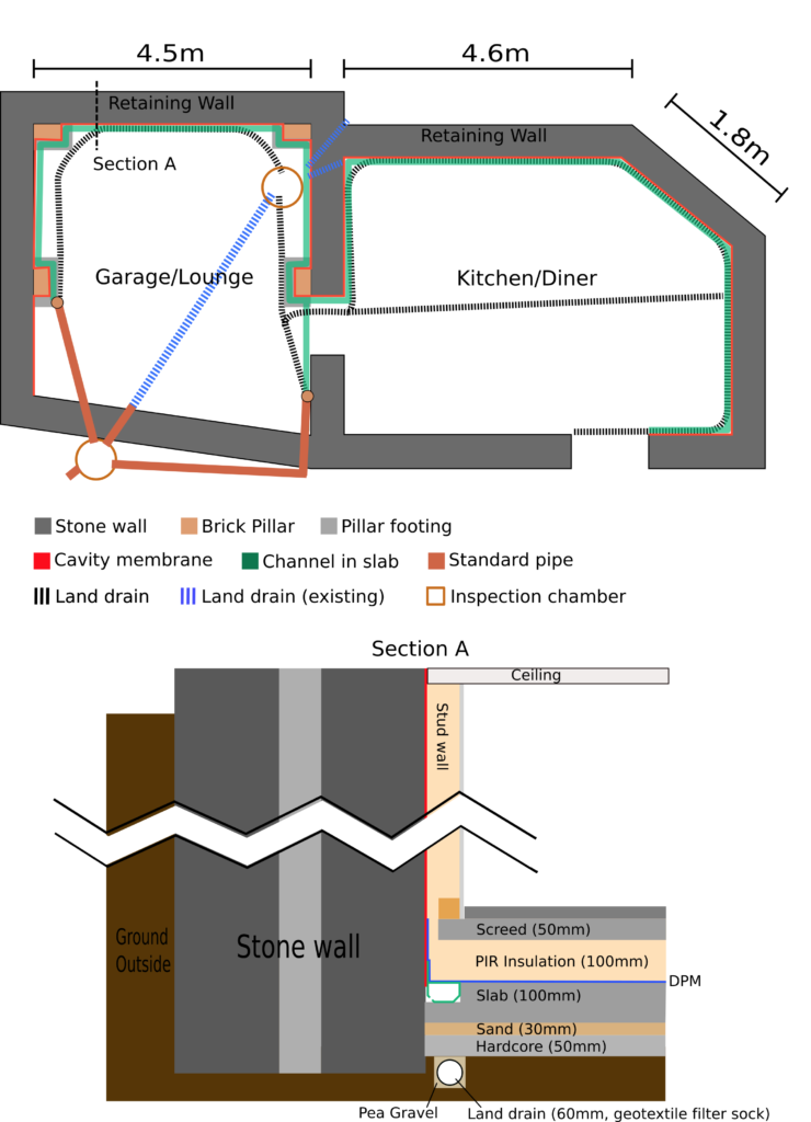
With hardcore in, the next layers to be added to the floor are sand and concrete. To prepare for this, several things needed to be done, including installing the inspection riser for the garage drain and designing and implementing a method to form drainage channels around the edge of the concrete.
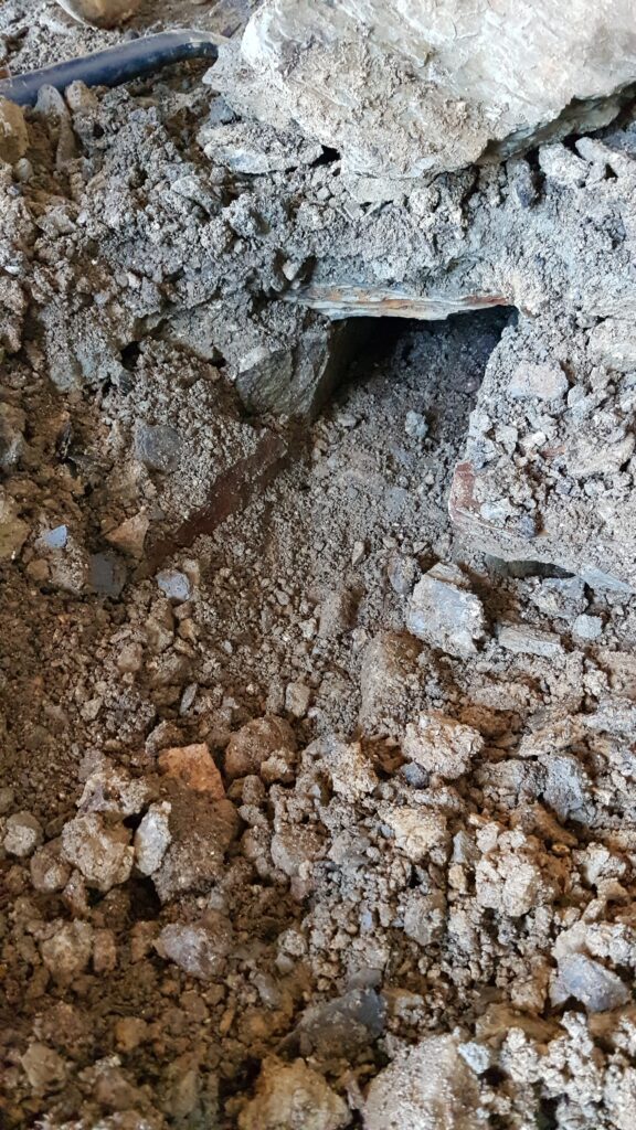
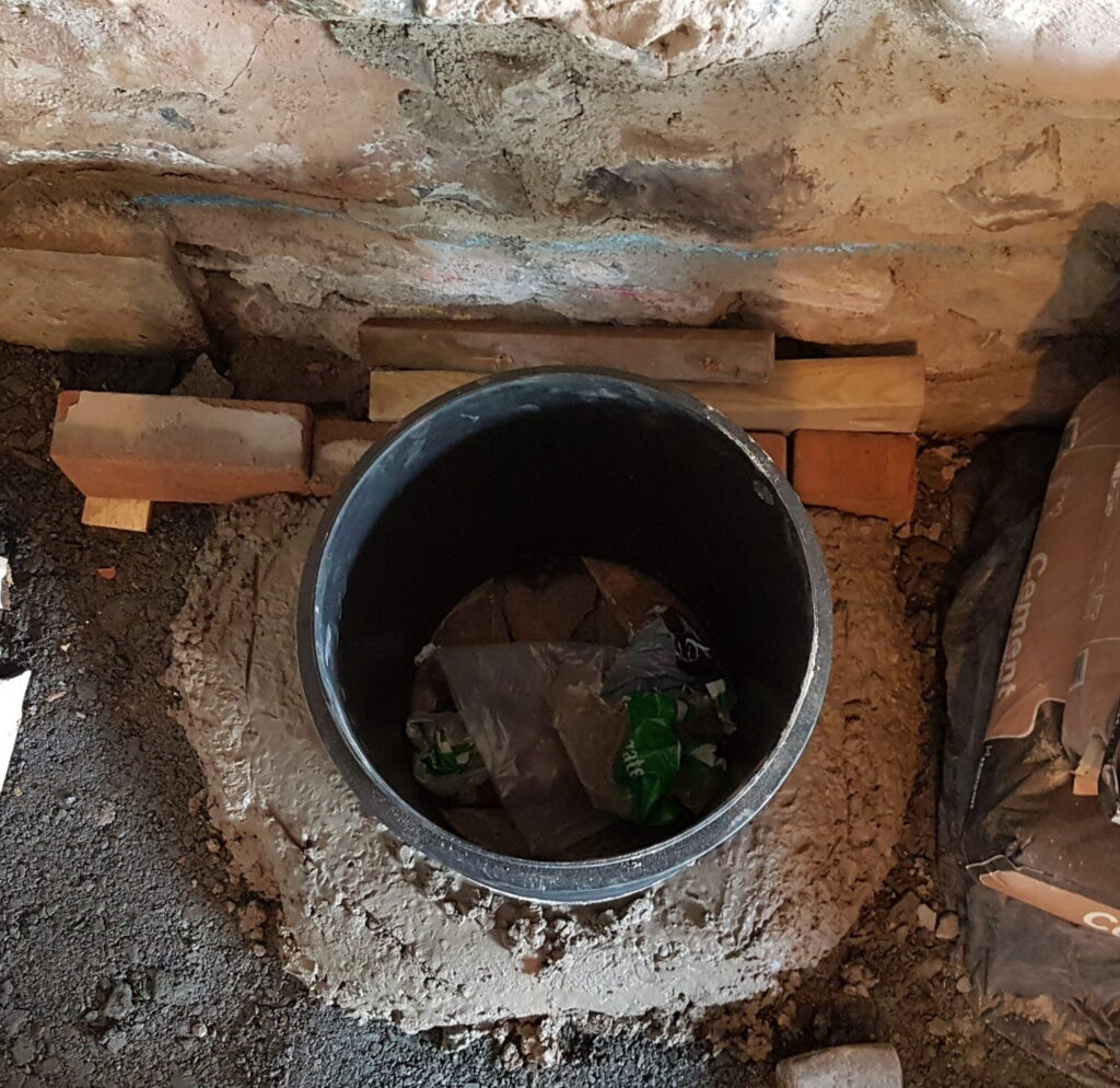
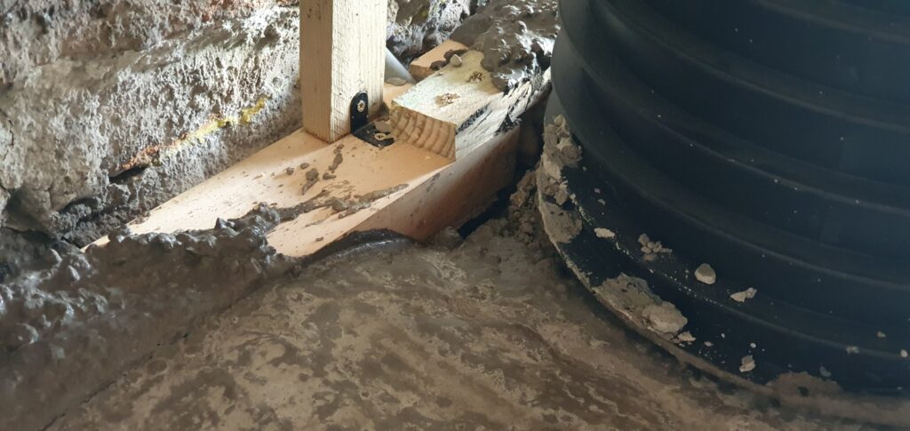
The inspection riser would be secured with concrete in advance to prevent it from moving when the subfloor concrete is poured. It had to be positioned just right over the concrete trapezium we had previously created to allow maximum space for access to the pipes below, but leave a wide enough gap against the wall so that a plastic drainage channel could pass by. The plan was to concrete in the front and sides of the inspection riser, so that behind the riser would be poured with the rest of the concrete forming a lintel that was part of the concrete subfloor. This lintel would be steel-reinforced, and support the plastic drainage channel running by the wall.
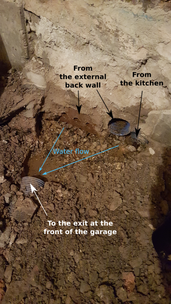
To shape the concrete, bricks were used to fill the void of the trapezium, with pieces of board placed on top. We wanted as smooth a finish as possible, but had to make it possible to remove the former through the inspection riser once the concrete had set. We added a small pipe behind the riser so that the drainage channels here could empty into the garage drain. This would prevent water needing to travel to the new drains at the front of the garage, via drier walls of the house. After this, the inspection riser was held in place while concrete was shovelled and shaped around the bottom at the front and sides, leaving the back to be filled by the floor pour. The excess concrete was later chipped away.

Once this was complete we could begin working on the drainage channels around the edge of the concrete slab. All the literature surrounding Type C waterproofing (the type we are installing) states that if a new concrete floor is being poured it is best practice to mould channels into the edges of the new concrete slab. It does not, however, give you a clue as to what methods to use to achieve this. Having discussed it with many people, including a builder whose previous line of work had been installing these waterproofing systems, we discovered that nobody had ever needed to do this before – despite Type C waterproofing being fairly standard practice in many basement conversions. Nobody knows the answer.
So we had to work it out for ourselves. The usual way to make voids in concrete is to make formers of the shape you desire. We wanted a channel most of the way around the edge of the concrete, but not all the way through it – there needed to be concrete under the channels. We had to ensure the bottom of the former remained at the depth in the concrete that we wished the channels to be formed at. If the former sank in the wet concrete, the channels would be covered in concrete, and if it floated, the channels wouldn’t be deep enough to accept the plastic channels typical of type C installations. To make life even harder, the channels have to be almost perfectly level; low spots would result in water collecting, rather than draining away.
We settled on using lengths of timber. We could attach these to the walls at the correct height using L-brackets and upright pieces of wood. To minimise drilling into the stone, these uprights could be attached to horizontal lengths that we had already attached to the stone wall. Why, I hear you ask? The attachment method for the cavity wall membrane involves drilling through the membrane into the stone. The membrane is then attached to the wall using large, fancy, plastic “nails” (for want of a better word). They are officially called “brick plugs”. These brick plugs have a rubber ring that is compressed when they are sunk into the wall. This seals the hole you have created, but only if the rubber ring can compress fairly uniformly. Here’s a riveting corporate video of the process.
Stone houses notoriously do not have flat surfaces, so our plan is to render strips along the wall to create some. Which brings us to the wood. The pieces of horizontal wood had been added to create a guide for applying the render strips.
Our channels need to be at least 50mm deep, and about 100mm wide, so that the plastic channel will fit snugly. Conveniently, you can buy wood in 100mm by 50mm lengths – exactly what we needed. So we calculated the length of wood we would need based on the length of the intended channel, and made an order. They gave us the choice of rough sawn or planed. We chose planed as this would give us a smoother finish to the channels, and probably be easier to remove once the concrete was set.
When it arrived, it looked a little off, so we gave it a measure. Here’s something worth knowing for the future: If you order wood that is labelled 100x50mm, it is not always 100x50mm. Ours was about 93mm by 43mm. When we talked to Ethan’s dad, he told us the standard for planed timber is to have 100x50mm and THEN plane it.

So here we were with 30m of former that was too shallow. We could probably get away with the width (the plastic channels are 50×80 and the membrane that needs to go behind is about 10mm). But we definitely didn’t want the plastic channels sticking 7mm above the concrete, and as we were needing to add a waterproofing slurry to the channels it might actually end up being more like 10mm.
So we needed to add some depth. Ethan’s dad picked up some 9 mm ply. We would cut it into strips and tack it onto the bottom of the 93×43 timber, making it 93×52. Also, the walls in the house are by no means straight, so in some areas we where water often runs down the wall we can shape the ply to meet the wall; this would stop the wet concrete rising up behind the former, creating an additional barrier for the water to flow over before reaching the channel.
While hammering the tacks to attach the ply, I started to receive tips on my cautious hammering techniques. I was holding the hammer too close to the head, and should hold it at the end for easiest use. I explained that I was working up to that as it had been a while since I used a hammer in earnest and needed to build my control and confidence. After saying I would gradually move my hand down the hammer as I built this, Ethans dad grabbed a panel pin, put his fingers either side of it against the wood and told me to hold the end of the hammer and hit the pin. His reasoning: “I wouldn’t hit *his* hand”. Everyone knows that the only reason people hit their own hands while they’re hammering is because they just don’t worry about their own hands enough, whereas someone else’s… After repeatedly assuring him that I WOULD in fact hit his hand, and that I would NOT be making an attempt while he was holding the pin, I was left to my own devices. Until Ethan walked in: “You know it’s easier if you hold the hammer at the end.”
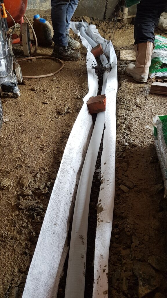
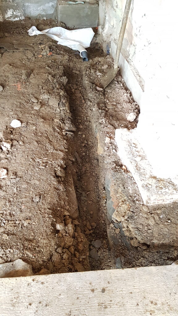
Having experienced my death stare, and just a small amount of snapping, Ethan left the room to continue working on the drainage pipes. The pipes coming up through the hardcore were positioned to allow for the channels to be drained by gravity. They aren’t vertical, so Ethan had to cut them diagonally so that they could meet flush with the wooden channels. We stuffed them with plastic to stop as much concrete or cement pouring down as possible. To stop them moving when the concrete was poured, we used the same L-brackets that we used to connect the uprights to the channel formers, bent into a sort of “claw”. Of course we couldn’t screw them to the pipe, so we relied on friction.
After the hammering was over, and the pipes were prepared, we painted mould oil onto the formers (to make their later removal from the set concrete easier) and attached them to the wall. This took longer than you’d expect. As mentioned earlier, they had to be almost perfectly level, both along the wall and in terms of tilt. This involved using a laser level, a hammer to adjust the L-brackets, lots of detaching and reattaching, and eventually a lot of “that’s probably as close as we’re gonna get it”.
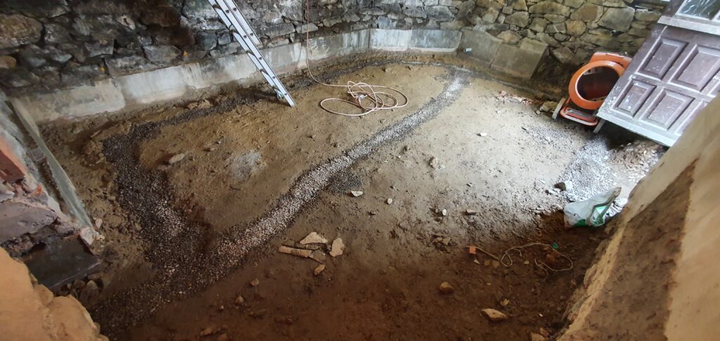
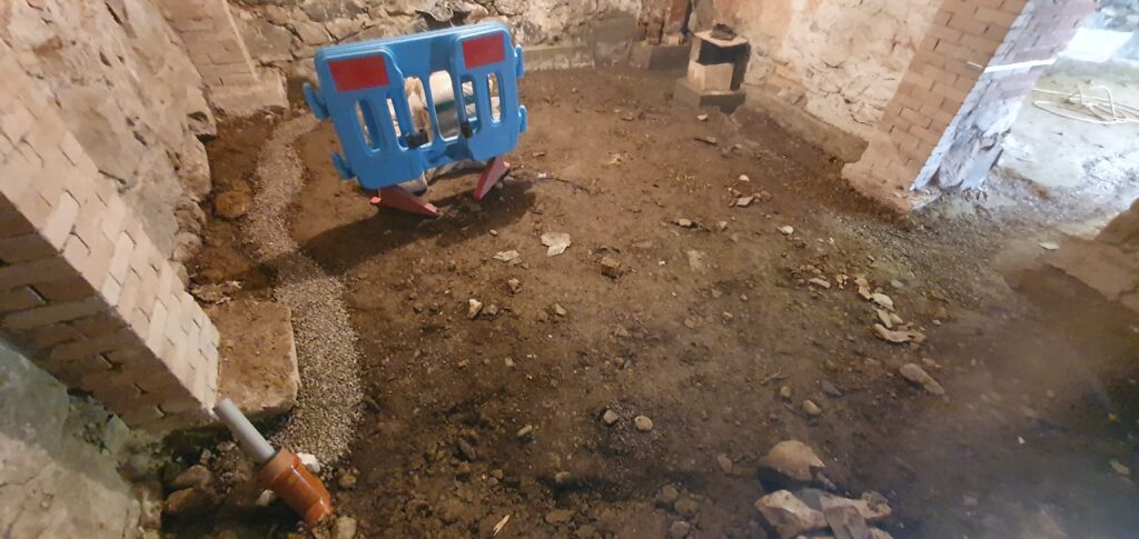
The whole thing was a long drawn out process, and I think due to the struggle, we didn’t take the time out to take intermediate photos. But here are some pictures of the final product:
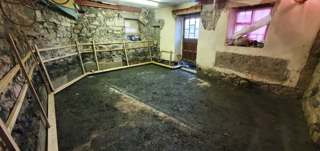
Kitchen/diner 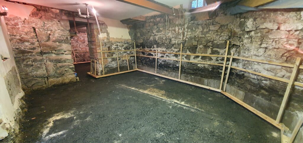
Kitchen/diner 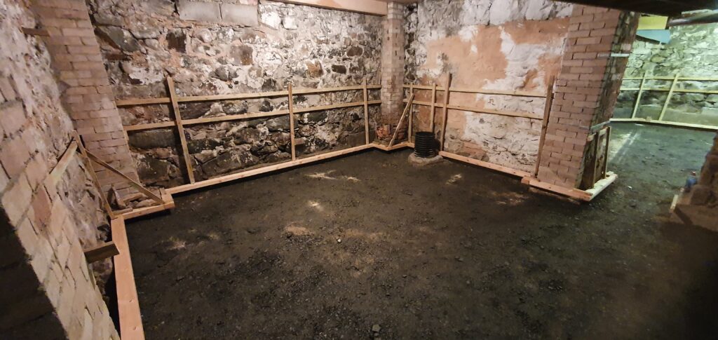
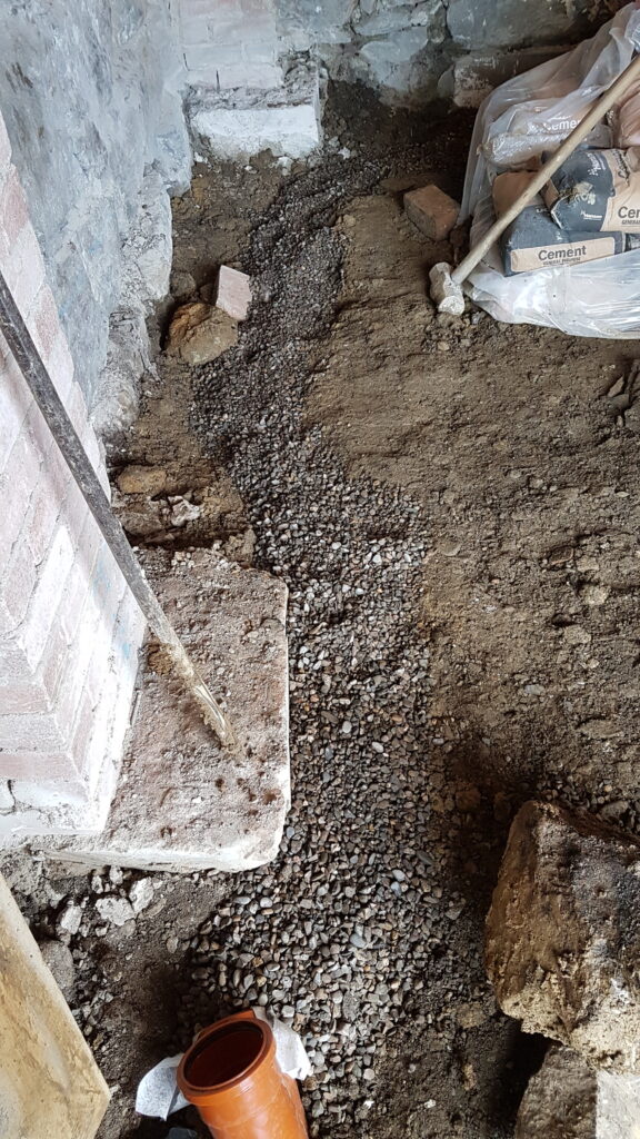
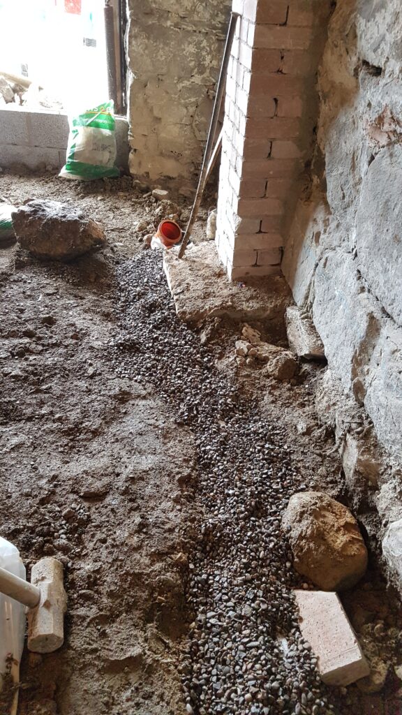
Garage/lounge 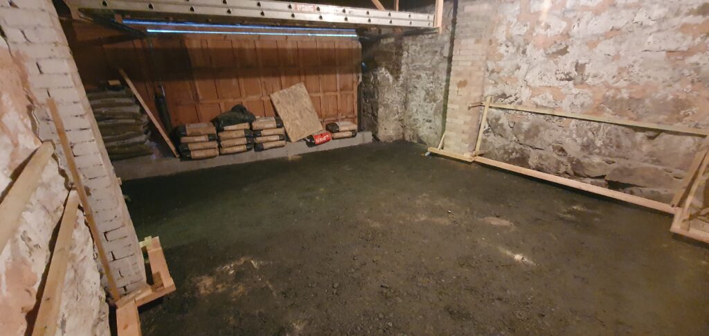
Garage/Lounge 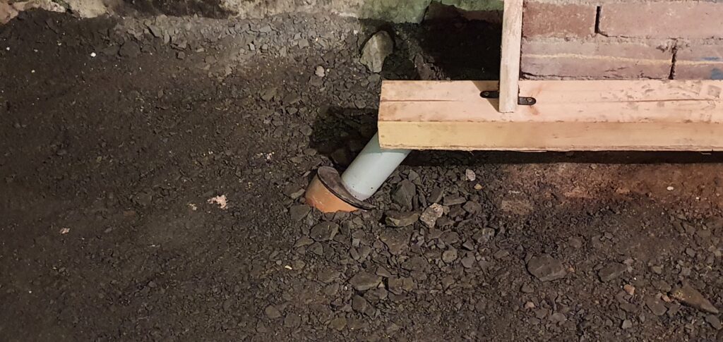
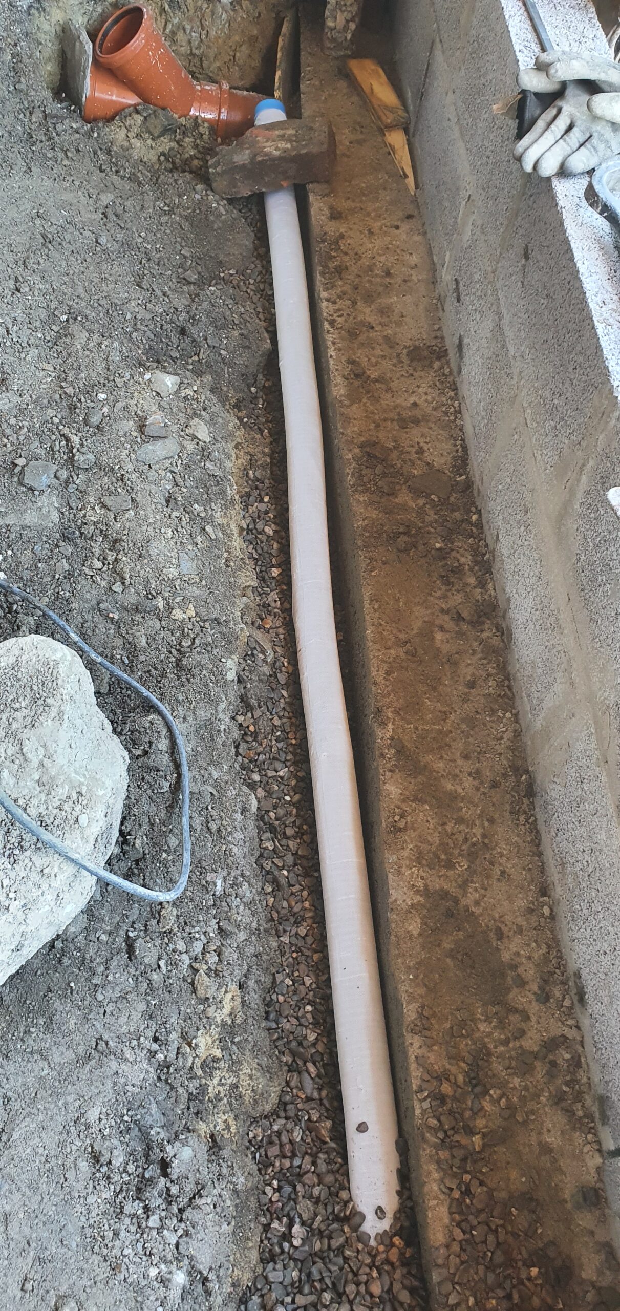
Pipe in the far side of the garage/lounge 
Pipe out the front door 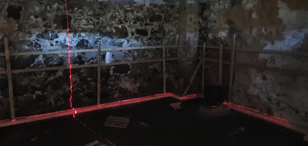
Laser levelling the channels
After the concrete had been poured it looked like this:
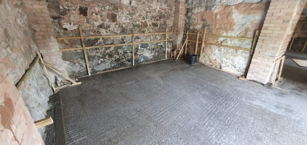
Garage/lounge 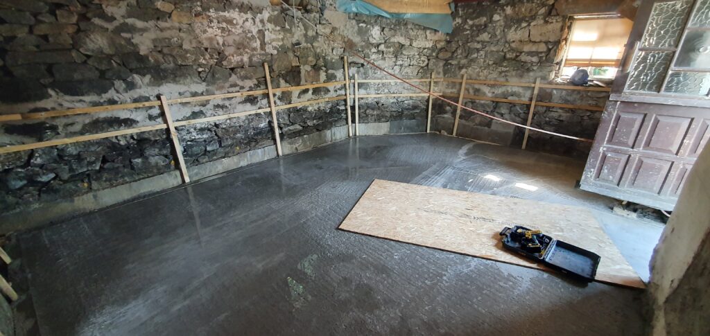
Kitchen 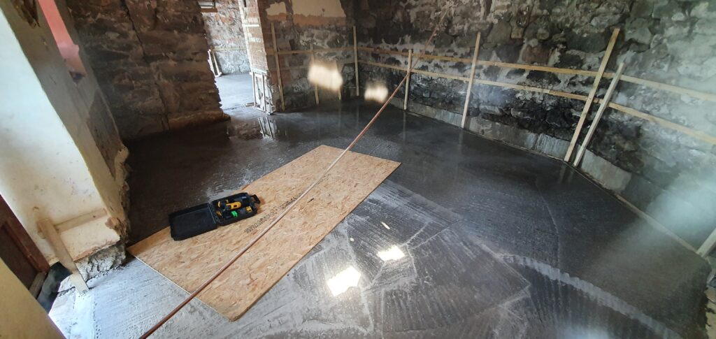
Kitchen 
Wet floor in kitchen
The floors had puddles of water, which is apparently quite normal for curing concrete. It certainly didn’t help that water was pouring in the back wall and had nowhere else to go due to the wood in the new channels.
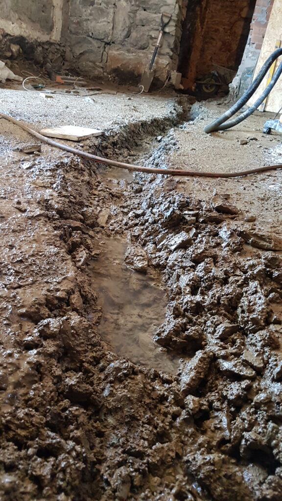
In any case, we were quite excited by the rising level of our floors. Layers had finally started building up! Then we noticed something else rising: the soakaway. We hadn’t warned them, because we had thought it looked fairly obviously like drainage works in progress – we won’t be making that mistake again. They had allowed the concrete lorry to rinse out into the soakaway, leaving cementy, silty water to penetrate who knows how deep, blocking all of the tiny holes. Another evening of hoovering, and trying to remember exactly where the water level had previously stabilised really took something away from the excitement of finally having a solid concrete floor.

Once we had gotten over the soakaway panic, we also noticed something else they’d missed:
The concrete had not flowed below the wooden channel behind the inspection chamber. So while they *had* remembered to place a reinforcing bar across where the concrete lintel should have been, it was certainly not surrounded with concrete. This would need to be fixed.

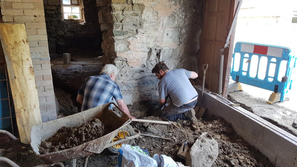
We temporarily ignored that issue, and continued with the plan. Before the concrete got too hard, and the wood got more wet and swollen, we began removing the wood from the channels. Here are Ethan and his dad removing the first section:
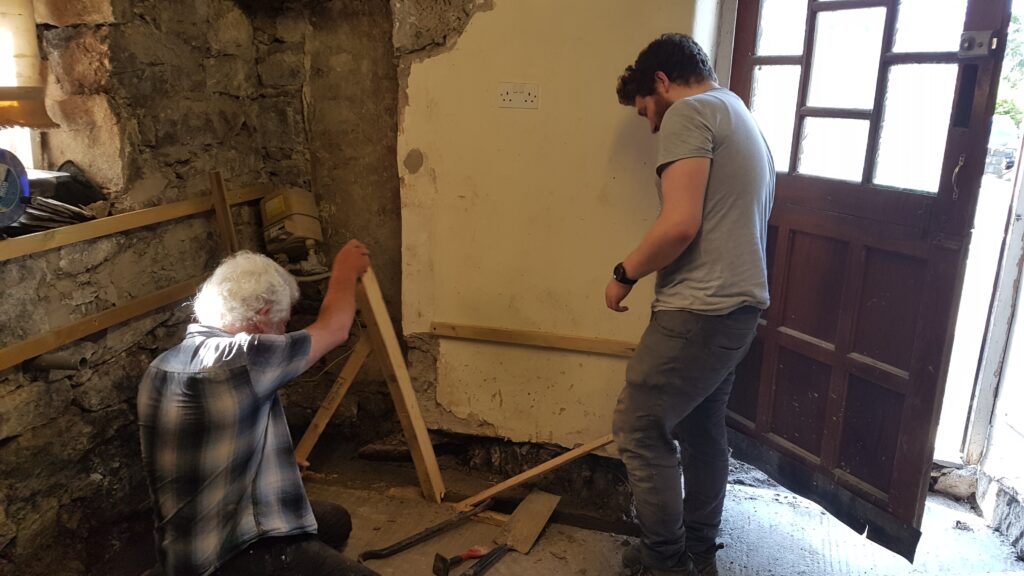
It was not an easy job, and it certainly seemed like the mould oil that we had painted on in an attempt to make it easier was not working. A tip: try to void using ply in situations like this, it soaked up water like nobody’s business and swelled, wedging itself tightly in the concrete. Eventually though, with enough brute force, all of the wood was removed from the new concrete channels.
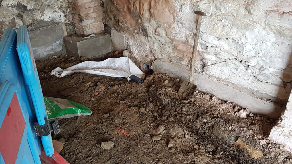
The channels themselves appeared relatively well made (if we do say so ourselves), with most areas being surprisingly smooth. There were a few voids and misshapen areas, but nothing too serious. The pipes had also stayed in place and very little digging was required to clear them.
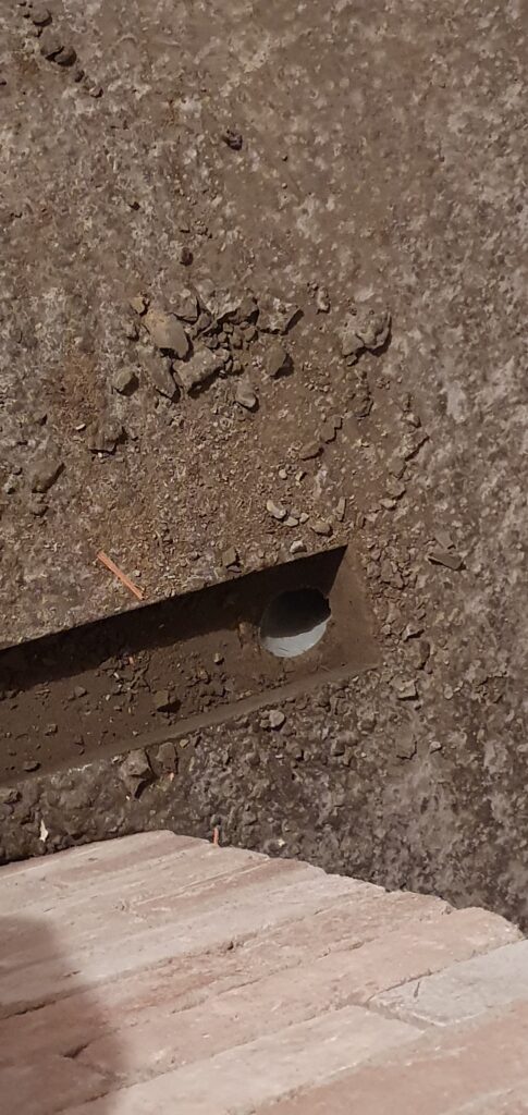
Pipe in the far side of the garage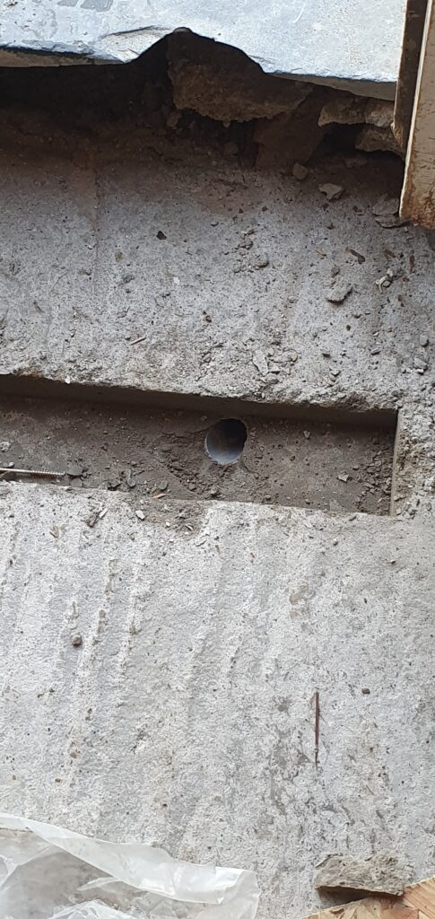
Pipe near the front door
Once the channels were freed, the water on the concrete cleared fairly quickly, as it had somewhere to flow, and all new water from the back wall was captured. The drainage plan is finally coming together!

Next step: cavity wall membrane – I’m sure it will all go as smoothly as the corporate video would imply.